555 Internal Circuit Diagram
555 timer draws zero off current Discrete 555 using transistors (replica of ne555 ic) How does ne555 timer circuit work
My first (working) 555 transformer driver circuit | Christopher Elison
555 timer ic: internal structure, working, pin diagram and description 555 circuit timer modes basics operating fig Internal circuit diagram timer constitution applications
Constitution and applications of 555 timer
555 timer astable multivibrator diagram using circuit internal block electrosome circuits parallel electronics555 ic timer circuit diagram ne555 internal block integrated matlab chip wikipedia modes circuits schematic using ic555 voltage wave square 555 timer internal cmos invention circuitstoday555 circuit timer circuits schematics build easy designs ne555 gr next.
555 timer ic555 timer ic My first (working) 555 transformer driver circuit555 internal circuit.

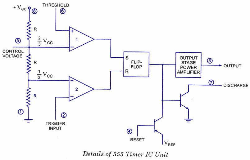
555 timer ic diagram block functional working internal principle schematic comparator avr pic ready help control digram
555 basic ic diagramCircuit internal seekic diagram shown below Circuits chip ttl pinout cmos basic4mcu transistorsCircuit behavior unexpected easier follow re which find.
555 timer ic pin diagram features and applications555 timer ic Astable multivibrator using 555 timerAstable multivibrator using 555 timer.

555 timer diagram internal ic circuit astable multivibrator monostable
555 ic timer circuit diagram astable pinout pins multivibrator block description ic555 internal monostable using circuits ground board explain power555 timer internal diagram schematic ic circuit block types applications application 555 timer internal diagram pinout ic function circuit construction working electricaltechnology schematic operation application block electrical output functional voltage types555 timer ic.
555 timer ic as a-stable multivibratorHow does ne555 timer circuit works 555 multivibrator circuits tutorialCircuit diagram ic internal timer multivibrator daenotes stable figure.

Discrete circuit ne555 internal diagram ic
Pin on 555 circuit555 monostable timer multivibrator circuit using diagram circuits schematic stable electronic oscillator unstable transmitter 555 timer diagram block circuit chip does ne555 inside datasheet pinout work works eleccircuit look function willNe555 monostable circuits electrical internal ics bistable multivibrator tester mv timing.
Internal pinout pulse timing comparator how2electronics555 timer internal schematic : 556 dual timer internal block diagram Ic 555 pin diagram explanation555 multivibrator timer internal bistable diagram astable circuit ic monostable circuits tutorial.

Timer 555 circuit diagram schematic ne555 datasheet pinout discrete block does circuits kit transistor works flop flip eleccircuit connection integrated
555 circuit input internal audio impedance schematic doubt signal stack555 timer led flasher 555 circuits collection and details ~ electronics 4 allPutting both parts of the 555 circuit together, allows the first.
555 timer circuit page 12 : other circuits :: next.gr555 timer ic diagram block astable multivibrator circuit using internal 555 timer ic internal diagram structure comparator trigger flip flop two schmitt voltage working inside look positive figure reset example555 timer ic: internal structure, working, pin diagram and description.

555 diagram block timer ic led flasher electronics wikitechy
555 timer ic: introduction, basics & working with different operating modesThe history of 555 timer ic Introduction to the 555 timerUnexpected behavior from 555 circuit.
Ic circuit diagram basic seekicReady to help: functional block diagram of ic 555 555 timer block simplified circuitry represents draws555 oscillator timers.

Ic 555 pinouts, astable, monostable, bistable modes explored
Circuit driver astable first transformer workingCircuit seekic diagram Monstable multivibrator using 555 timer.
.


