555 Timer Circuit Diagram Pulse Generator
Astable 555 timer schematic / astable multivibrator using 555 timer 555 timer clock pulse generator How to make pulse width modulation circuit wiring view and schematics
555 Timer Basics - Monostable Mode
555 timer ic pin diagram explanation 555 timer ne555 eleccircuit pinout datasheet Simple 555 circuits explained: 555 timer circuit, 555 electrical pulse
Pulse generator timer circuits
555 circuit timer circuits simple generator pulse schematics electrical voltage monitor diagram build easy explained vr1 r1 c1 diy555 timer monostable circuit triggered when circuit is powerd Pwm ic pulse modulation generate circuitsCircuit 555 pulse timer diagram basic projects circuits project simple electronic gr next.
Generator 555 pulse timer circuits gr next schematic visitSimple pulse generator circuit by ic 555 timer Pin on electronic circuits555_high voltage pulse generator using 555 timer and relays.

Pwm 555 circuit timer generator diagram ic using circuits pulse modulation width generation signal led circuitdigest generate modulator electronic dimmer
Schematic 555 timer circuit diagram / lm555 electronics schematic555 timer basics 555 monostable timer circuit trigger shot time multivibrator electronics delay edge triggered watchdog when input reset tutorial window using diagramHow to build a clock circuit with a 555 timer.
Pwm 555 timer circuit width modulated generatingMultisim timer Ic 555 pwm generator- a look into pulse width modulation circuitsGenerating pwm pulse width modulated wave using 555 timer ic.

555 timer pulse generator under timer circuits -6854- : next.gr
555 timer monostable circuit variable diagram mode shot led resistor potentiometer pulse 10k off basics use connect bistable time turn555 circuit circuits pulse generator simple timer diagram voltage schematics electronic diy tone electrical easy used Free circuit diagrams: timer 555 schematicThe 555 timer schematic diagram.
555 timer pwm pulse modulation generate ne555 circuits buzzer alarm amp555 astable circuit oscillator timer arduino frequency ic pwm 40khz electronics multivibrator wave square pulse electronic signal halve capacitor mode Electronic projectsGadgets projects electronics.

Generate pulse width modulation (pwm) signal using 555 timer ic
Timer 555 circuit schematic electronic ne555 circuits control lm555 applications multivibrator ic relay using off switch generator simple charger next555 pulse generator module, how it works Circuit pulse diagram moter generator pcb diagrams build555 timer clock circuit schematic build circuitos con using learningaboutelectronics 60hz resistor esquemas will breadboard produce shown below.
555 timer schematicPulse pwm circuits 555 pwm ltspice timer mathscinotes implementationTimer light dancing rangkaian lampu disko schematic electrosome easyeda skema lm555 chip electro.

555 circuit diagrams
Generator pulse 555 circuit diagram sponsored links circuitdiagramSchematic 555 timer circuit diagram / lm555 electronics schematic Generate pulse width modulation (pwm) signal using 555 timer ic[free download] timergenerator circuits manual.
555 generator timer pulse ic simple circuit circuits electronic oscillator diagram projects ne555n voltage wiring digital arduino electronics use grPwm 555 generator timer circuit stack How does ne555 timer circuit work555 timer multivibrator monostable ic lm555 astable stable experimental unstable.

Astable timer: halve frequency while maintaining the same "up" pulse
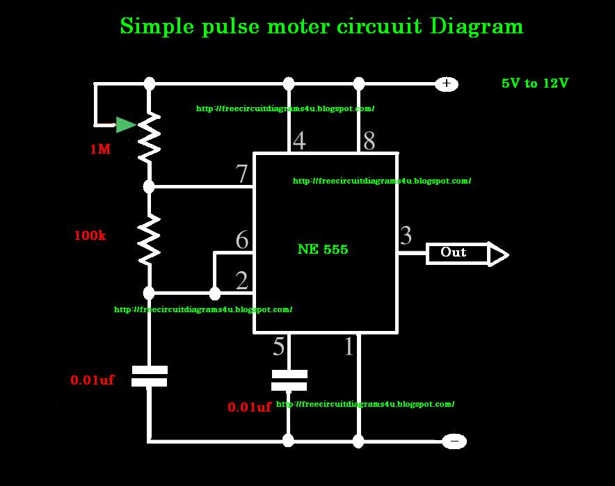
Timer schematicGenerator pulse 555 circuit simple motor diy pwm dc manual stepper driver cnc 555 pulse generator. simple circuit.Pulse moter circuit diagram.
555 pulse generatorSimple 555 circuits explained: 555 timer circuit, 555 electrical pulse 555 timer astable multivibrator learningaboutelectronics breadboard cycleGenerator pulse circuit 555 diagram duty cycle frequency adjustable ne555 variable ic electronic schematics circuits seekic projects timer diy 50.

555 pulse generator circuit
555 timer pwm generator555 astable circuit ic multivibrator timer using pulse generator help light diagram oscillator frequency circuits sensor mode needed wave square .
.


